Table of Contents
Experimental Design & Set Up
Part2: Analysis and Break Down of each Critical Component in Common Design.
Safety & Operational Hazards
Common protocols for handling gases and electricity.
- Carbon Monoxide (CO) Toxicity:
- Risk: The primary product of this reaction is CO, an odorless, colorless, and deadly gas.
- Protocol: Experiments should be conducted in a fume hood or a well-ventilated space equipped with CO detector.
- High-Pressure Cylinders:
- Risk: $CO_2$ tanks contain massive pressure. If it leaked or valve tear, it becomes a big projectile
- Protocol: Cylinders should be chained/strapped to a wall or stable bench at all times. Not moving a tank without the safety cap screwed on.
- Alkaline Electrolytes:
- Risk: Potassium Hydroxide ($KOH$) and Bicarbonate solutions can cause eye damage and skin irritation.
- Protocol: Chemical goggles and nitrile gloves to prevent any accidents.
- Electrical Safety in Wet Environments:
- Risk: Saltwater is highly conductive. Spills near the power supply can cause short circuits.
- Protocol: Power supplies should be kept above the bench surface and ensure that all alligator clips are dry before turning on the voltage.
Note that these are just some common safety and protocal when working with $CO_2$ reduction. There are other several guidlines which should always be looked up and followed for each chemical and instruments.
1. The Big Picture
For 90% of high school and undergraduate research, the standard design is the “H-Type Electrolytic Cell”.
H-Type Electrolytic Cell or commonly called “H-cell” gets its name from its iconic look, two container and a bridge, thus calling it H-Cell. Imagine two separate building connected by a bridge.
- Cathodic Chamber: This is where the \(CO_2\) reduction happens. It contains the Working Electrode and the \(CO_2\) gas.
- Anodic Chamber: This contains the Counter Electrode. Its job is just to complete the electrical circuit.
- The Membrane/Bridge: This allows ions to flow between the chambers but stops the liquids and gases from mixing.
Why separate them? If you put everything in one beaker, the oxygen produced in Anodic Chamber would float over to Chamber 1 and ruin your sensitive $CO_2$ reaction. The “H” shape physically isolates these compounds while allowing electricity to flow and reactions to happen.
(Note: There are also other types of Cells including Flow Cells and Single Cell. But, because Flow Cells are too advance and require expensive pumps and Single Cell will get all the liquid mixed up, we will left them out and focus on H-Cell. If you are interested, you can research further by looking into scientific papers regarding the Flow Cell pros, cons, and set up)
2. The Hardware Setup
To perform $CO_2$ reduction, you need a specific set of components arranged in a standard 3-Electrode System. This setup ensures we can control the voltage precisely while keeping the fuel products separate from the waste oxygen.
Interactive H-Cell
Welcome to the standard H-Type Electrolytic Cell. This is the workhorse of CO₂ reduction research.
Click on any part of the diagram (electrodes, membrane, bubbler) to learn its role.
3. Pre-Experiment Preparation
Before you assemble the cell, you must prepare the materials.
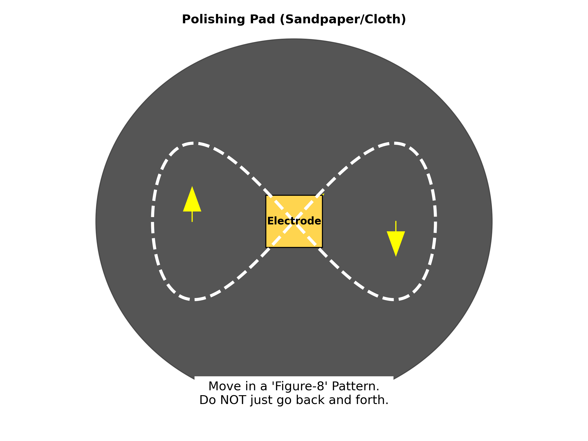
3.1 Polishing the Electrode
The electrode surface must first be atomically clean.
- Sand: Use fine-grit sandpaper to remove visible oxidation.
- Polish: Place a polishing cloth on a flat surface. Add Alumina slurry ($0.05 \mu m$).
- The Figure-8: Move the electrode in a “Figure-8” motion.
- Clean: Rinse with Distilled Water.
- Sonicate: Place the electrode in a beaker of water/acetone and put it in an ultrasonic bath for 5 minutes. This vibrates off the microscopic dust left by the polishing.
3.2 Membrane Hydration
The Nafion membrane acts like a sponge. If it is dry, it is brittle and non-conductive.
- The Rule: Never let the membrane dry out.
- Activation: Soak the membrane in your electrolyte or deionized water for at least 24 hours before use.
- Storage: Keep it in a sealed jar of water when not in use.
4. Assembly & Wiring
Once the parts are clean, assemble the H-Cell. Ensure the membrane is sandwiched tightly between the two chambers to prevent leaks.
4.1 The Wiring
Connecting the Potentiostat can be confusing because cable colors vary by brand; however, the logic is always the same:
| Cable Role | Common Color | Connects To |
|---|---|---|
| Working (WE) | Red | The Working Electrode. This is where we measure the reaction. |
| Counter (CE) | Black | Platinum Wire. This completes the circuit. |
| Reference (RE) | Blue | The Ag/AgCl. This measures the voltage. |
| Sense (S) | Often attached to WE | Connect this to Working Electrode as well to improve accuracy. |
*Warning: If you swap the Counter and Reference cables, you can instantly destroy your Reference Electrode by forcing high current through it.**
5. The Start-Up Protocol
You cannot simply turn on the voltage. You must first create the right environment.
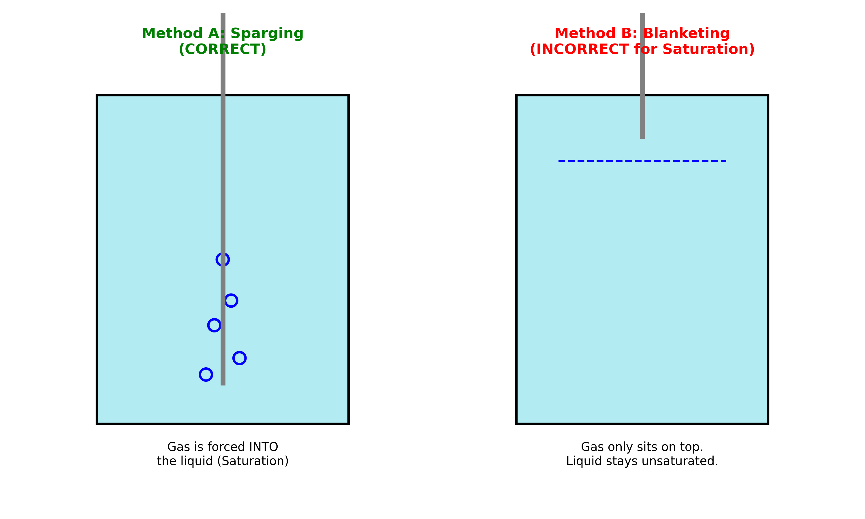
5.1 Purging
Air contains gases other than $CO_2$ that aren’t inert. They can react and steal the electricity from your CO2RR, so we need to remove them first.
- Insert the Gas Tube: Place the $CO_2$ gas tube directly into the liquid at the bottom of the cell.
- Bubble: Let the $CO_2$ bubble vigorously for 20-30 minutes before running the experiment. This ensures that the solutionus is saturated with $CO_2$ and every experiment is valid.
- Check: Ensure that the gas isn’t blanketting in the headspace and is sparging in the solution. Blanketting could starve your catalyst from receiving sufficient $CO_2$.
- Measure: Measure the flow rate of the $CO_2$ for each test typically by using mass flow controller. This is crucial for further calculation for accurate result.
5.2 The Leak Check
Before starting the electricity:
- Close the cell outlet.
- Apply soapy water to the joints.
- If you see bubbles growing on the outside, you have a gas leak. Tighten the clamps.
Conclusion
There is no universally “correct” $CO_2$ electrochemical setup. Valid designs are chosen based on research goals, constraints, and trade-offs. The best equipment is simply the setup that allows you to isolate the variable you are trying to study while minimizing sources of error like contamination or instability. Further information on the exact set up each experiment should be obtain from literature reviews and each consequence should be carefully considered before adjusting.